Discrete Sensors vs Distributed Fibre Optic Sensing
Experimental evaluation of strain, displacement, deformation, tilt and temperature monitoring using conventional discrete sensors and DFOS.
Explore the StudyMetallic Plates
Approx. 1 m × 1 m
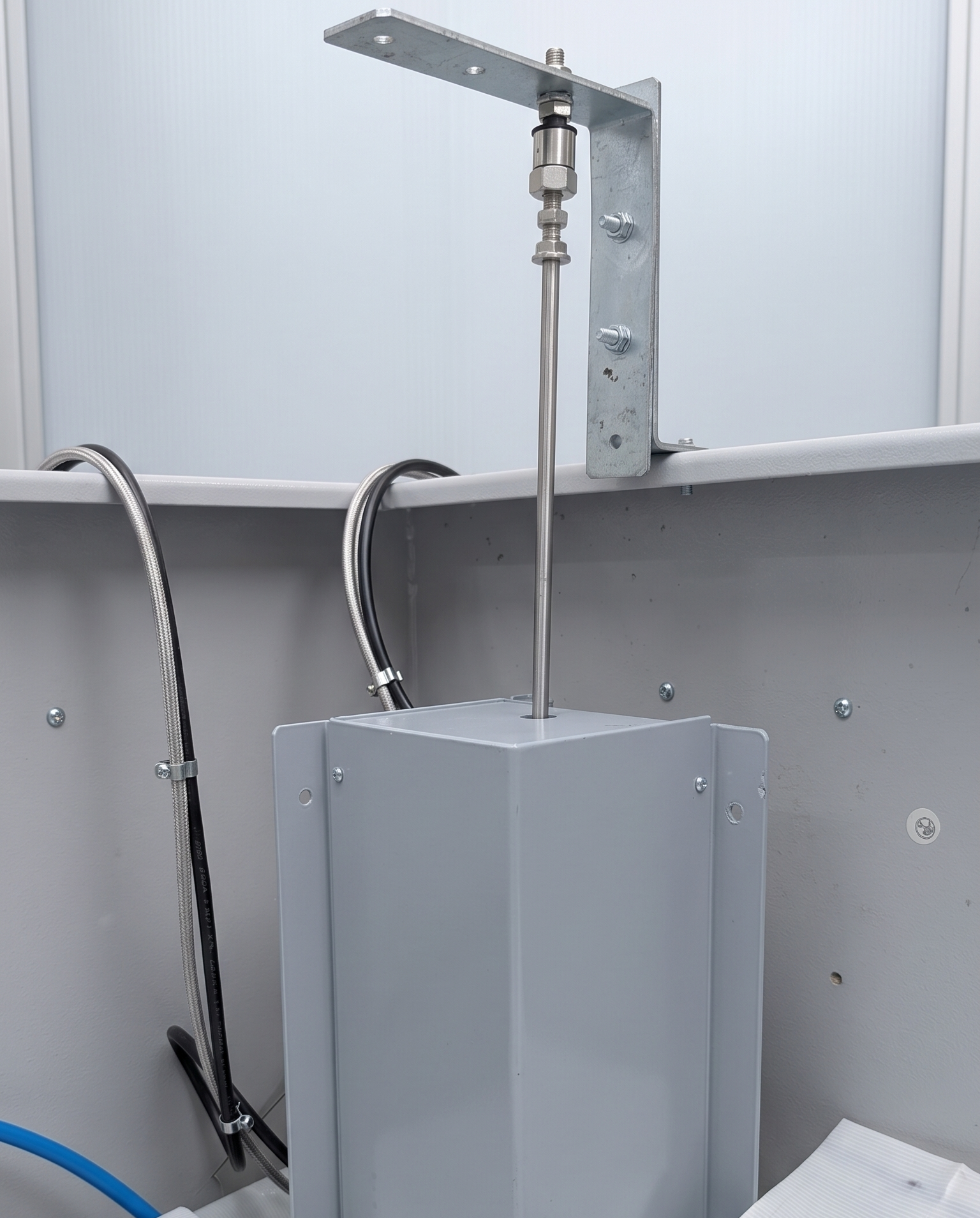
LVDT Sensors
Point displacement
Tilt Meter
Roll & pitch
PT100 Patches
Temperature
DFOS Cable
Test structure
From point monitoring
to structural awareness
Structural health monitoring is fundamentally a question of how much of a structure can be observed, how reliably it can be observed, and how early a change in structural behaviour can be identified.
Traditional structural monitoring systems generally use discrete sensors. These instruments provide valuable measurements, but each sensor observes a particular parameter at a particular physical location.
Consequently, monitoring performance depends strongly on whether the sensor has been installed at the right location and whether that location represents the behaviour of the entire structure.
Distributed Fibre Optic Sensing takes a different approach. Instead of treating a structure as a collection of isolated points, DFOS can treat the sensing fibre as a continuous measurement line.
What was the experiment
designed to investigate?
Compare discrete point-based sensing with distributed fibre optic sensing for structural parameter monitoring.
The comparison focuses on strain, displacement, deformation, tilt and temperature.
Strain distribution
Measure strain generated across a simulated structure.
Localized deformation
Identify high- and low-strain regions.
Displacement
Compare point displacement with distributed deformation.
Tilt & deformation
Compare tilt measurement with distributed structural behaviour.
Temperature
Compare PT100 point measurements with distributed temperature sensing.
System complexity
Evaluate cabling, electrical infrastructure and potential failure points.
Measurement stability
Assess signal stability and noise behaviour.
Real-world applicability
Evaluate suitability for landslides, cracks and structural monitoring.
Experimental setup
Structural deformation simulation
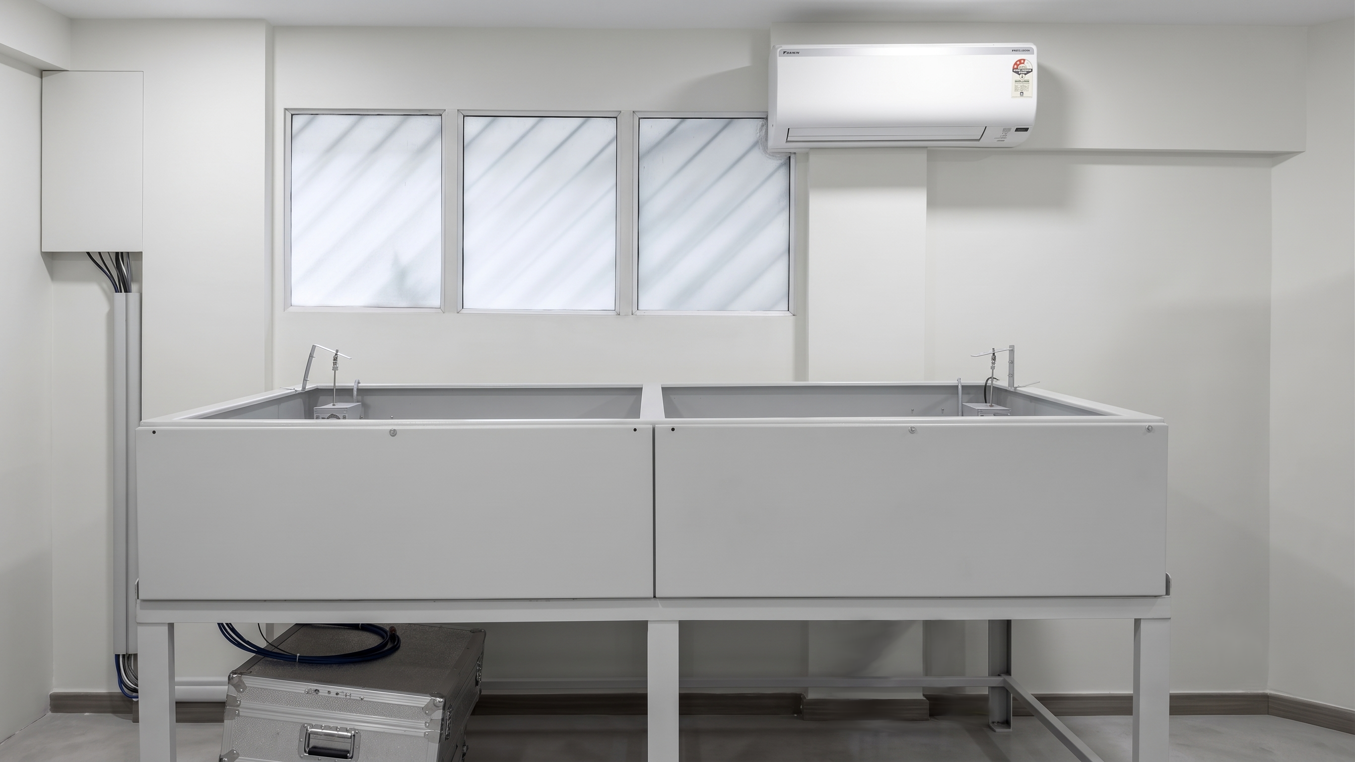
Two metallic plates, each approximately 1 m × 1 m, were arranged as a representative structural surface.
Tubes of different sizes were positioned beneath the plates and inflated or deflated during the experiment. These tubes acted as controlled actuators, producing localized upward displacement and deformation.
The deliberately non-uniform deformation created a controlled environment for comparing point-based and distributed monitoring.
- Differential ground movement
- Landslide-induced deformation
- Localized settlement or heave
- Crack development
- Differential bridge deformation
- Localized strain generation
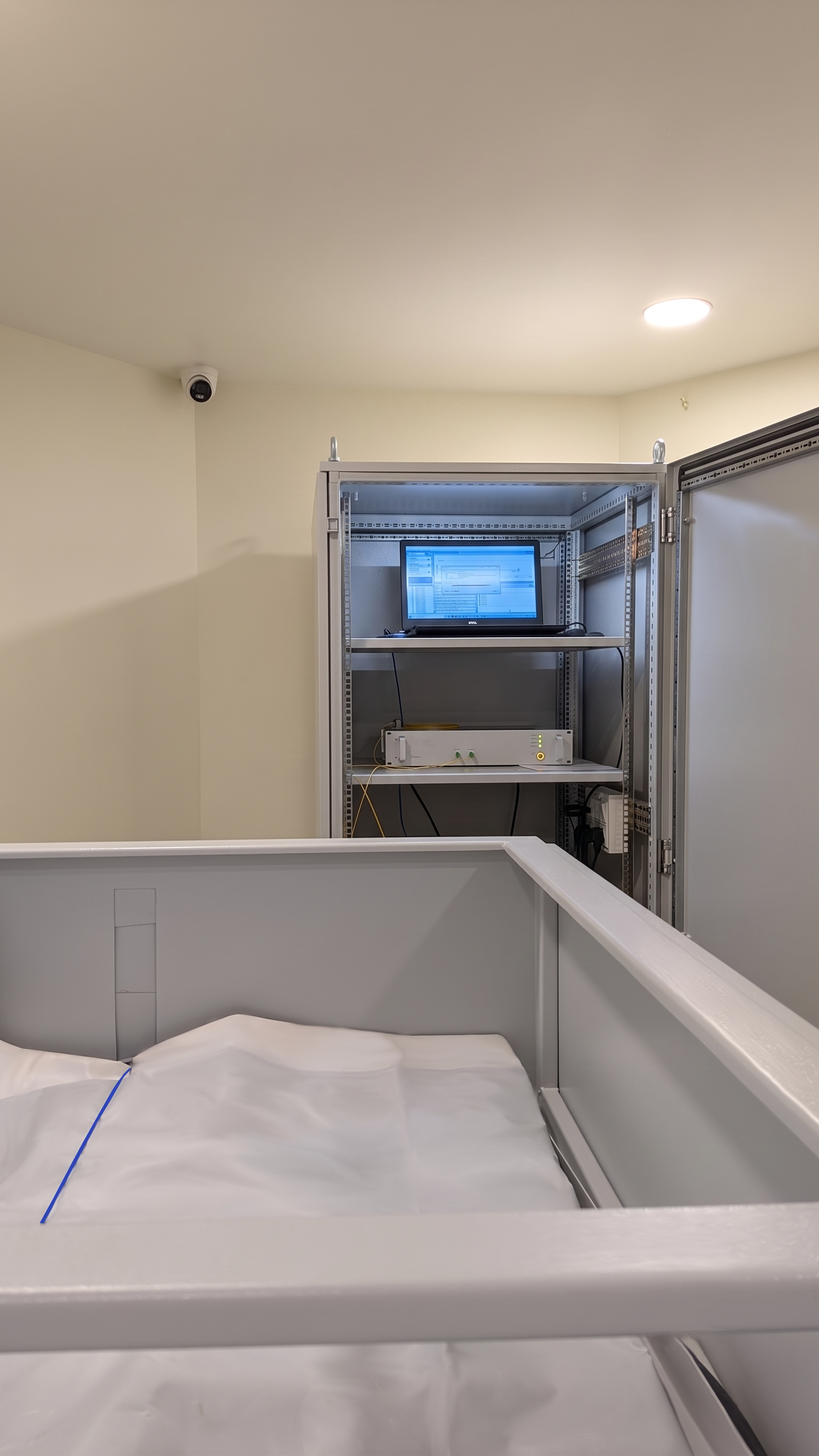
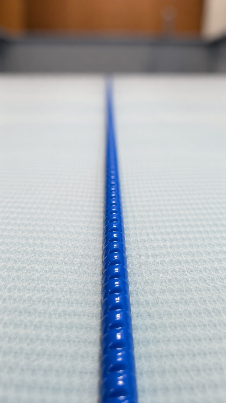
Controlled loading.
Measured response.
Inflation
Tubes beneath the plates increase in volume.
Deformation
The plates move upward with different levels of deformation.
Point sensing
Discrete sensors record parameters at their installation locations.
Distributed sensing
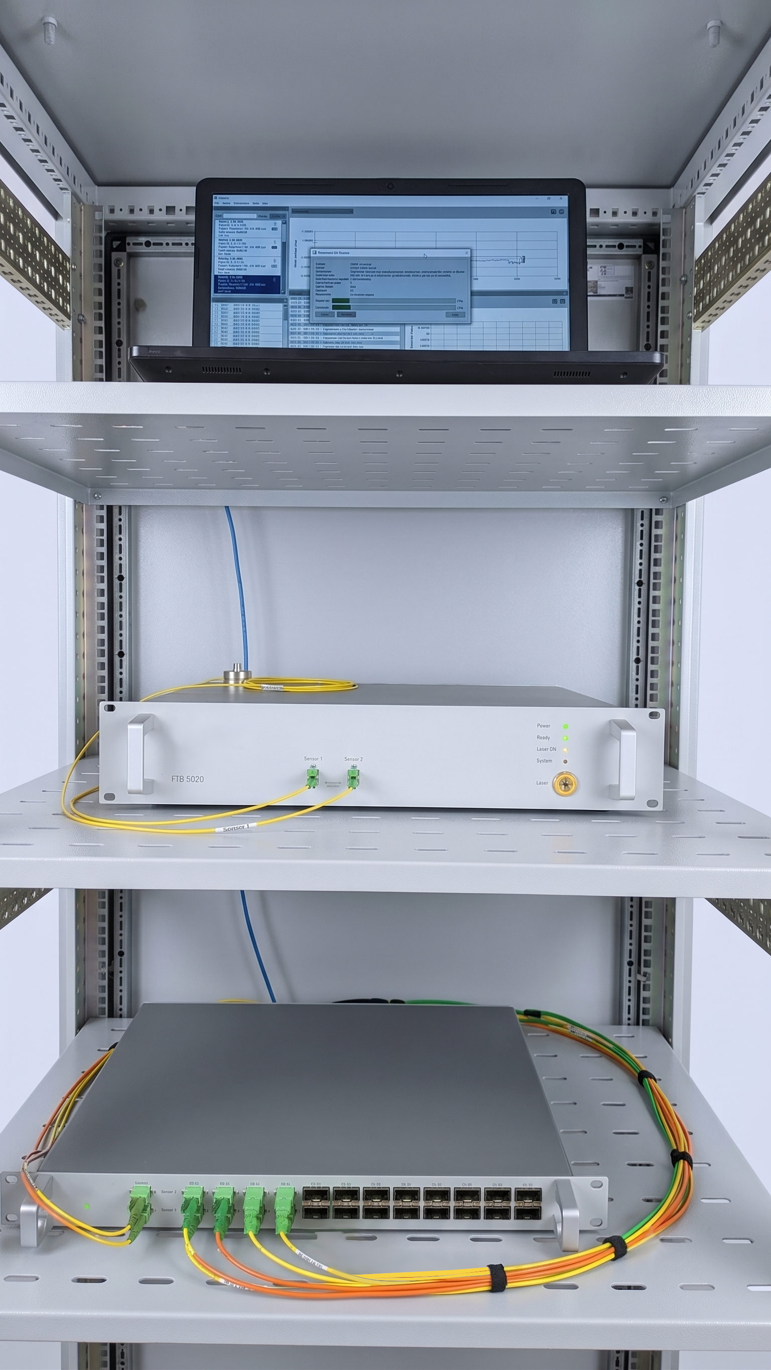
The DFOS cable records strain variation along the monitored length.
Deflation
The deformation reduces as the structure returns towards its initial condition.
Point measurements vs
distributed strain
Point observation
The LVDTs provide displacement information at their respective installation locations.
Distributed observation
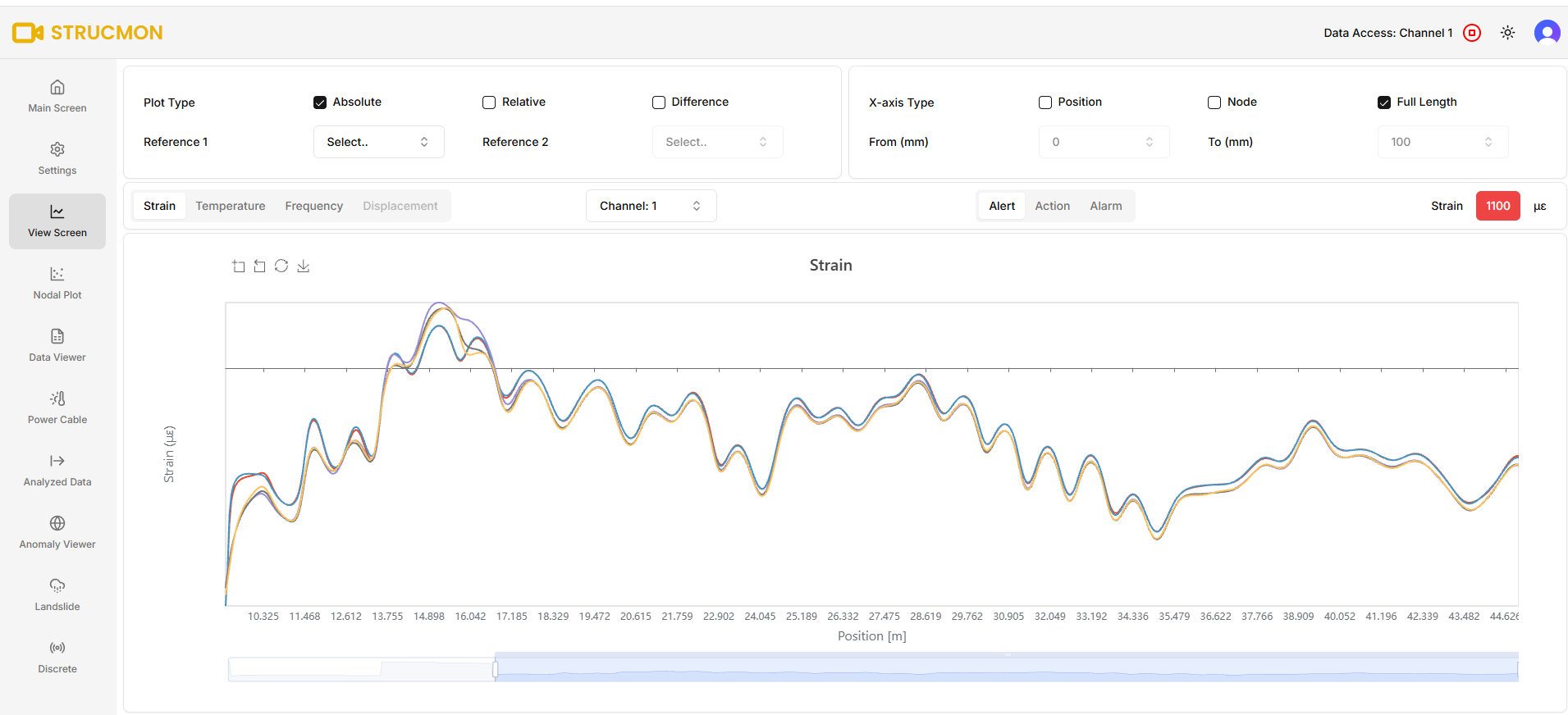
The DFOS cable generates a spatial strain profile, allowing regions of relatively high and low strain to be identified along the monitored path.
The important question is not simply “Which sensor is more accurate?”
A more meaningful question is:
“Which technology provides the information required to understand the structural behaviour?”One fibre.
Multiple thermal zones.
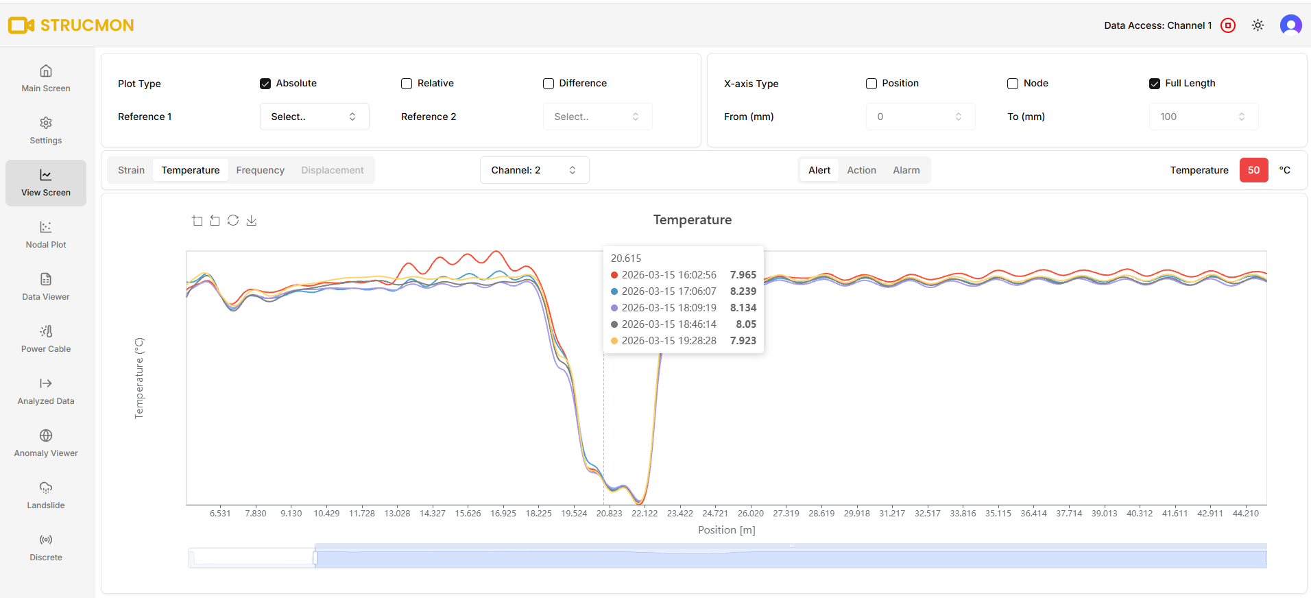
A separate experiment compared distributed fibre optic temperature measurement with discrete PT100 sensors.
Low-temperature zone
A portion of the sensing cable was coiled inside an ice bucket.
Elevated-temperature zone
Another section was exposed to a heating pad.
DFOS provided a stable temperature profile corresponding to the different thermal zones.
Discrete sensors
vs DFOS
| Parameter | Discrete Sensors | DFOS |
|---|---|---|
| Measurement philosophy | Point measurement | Distributed measurement |
| Spatial coverage | Limited to sensor locations | Continuous along fibre |
| Localized strain | Requires sensor near location | Identifies strain variation along sensing path |
| Displacement | Excellent at installed point | Interpreted through distributed strain/deformation |
| Tilt | Dedicated tilt sensor | Complementary deformation information |
| Temperature | Point measurement | Distributed temperature profile |
| Spatial resolution | Depends on sensor placement | Centimetre-scale in demonstrated system |
| Cabling | Multiple sensor cables | Single sensing fibre can cover extended region |
| Unknown deformation | Limited | Strong advantage |
| Maintenance points | Multiple electrical/sensor points | Fewer sensing-channel connections |
From laboratory
to infrastructure
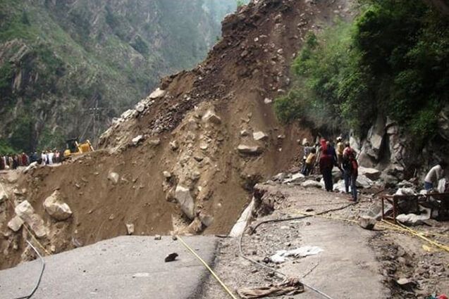
Landslide Monitoring
Identify progressive deformation, localized shear zones and changing strain along suspected movement zones.
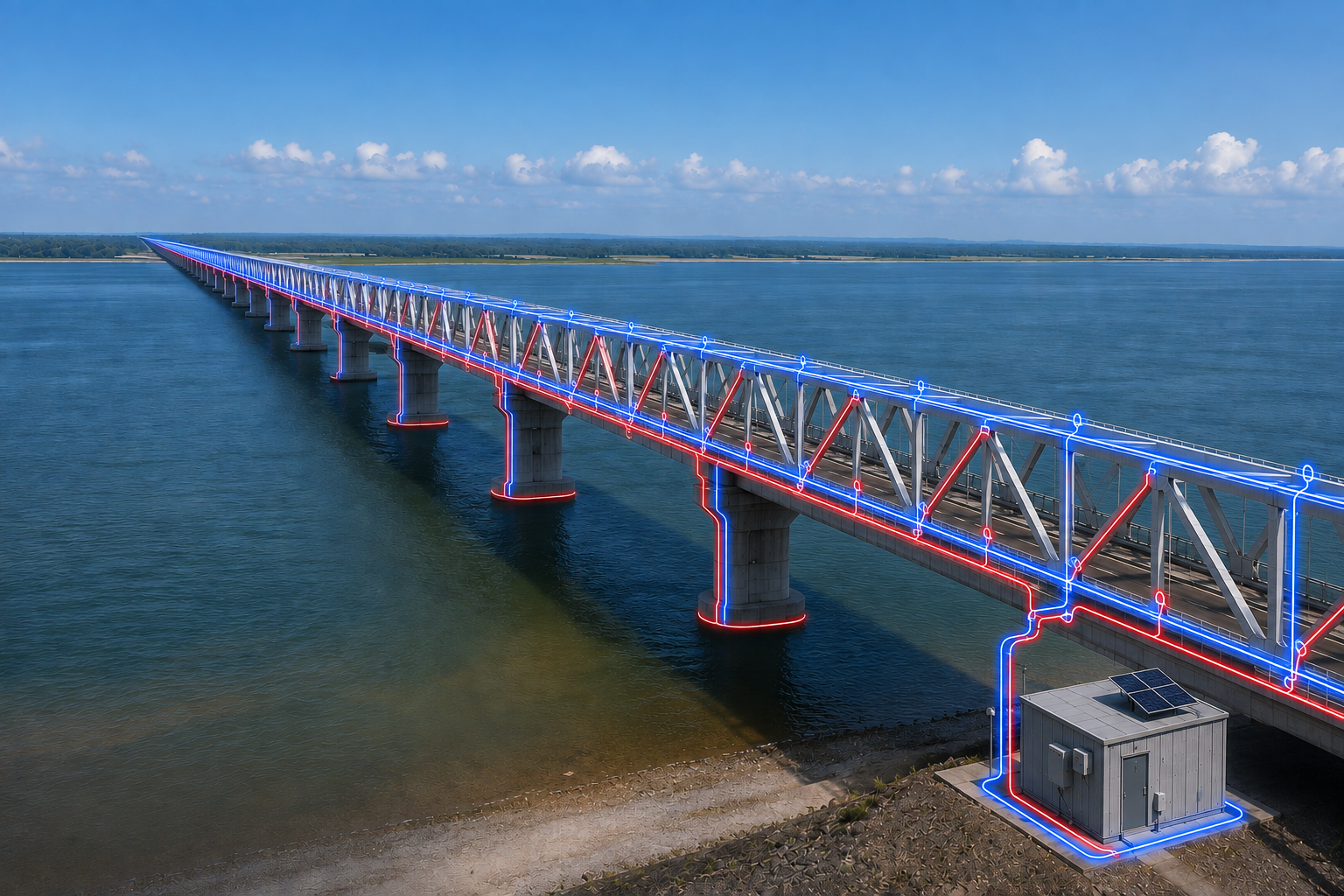
Bridge Monitoring
Observe changes in strain associated with bending, thermal expansion, localized deformation and differential movement.
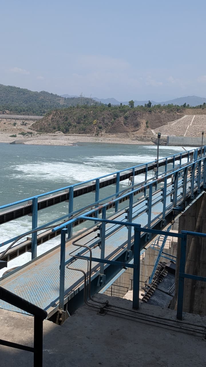
Dam Monitoring
Monitor distributed deformation across large structural regions.
Railway Infrastructure
Distributed sensing can provide extended monitoring coverage along infrastructure.
Pipeline Monitoring
Continuous sensing paths can help identify localized changes along long assets.
Crack-Prone Structures
Distributed strain monitoring can help identify localized structural anomalies.
A question asked
at a point.
“How much has this particular point moved?”
A question asked
along a path.
“How is the structure behaving along this region?”
Sensor-centric monitoring
→ Structure-centric monitoring
The sensing infrastructure can provide a spatial picture from which abnormal behaviour can subsequently be identified.
What the experiment
demonstrated
The experiment demonstrated a fundamental difference between discrete sensing and Distributed Fibre Optic Sensing.
Discrete sensors provided meaningful measurements at their respective installation locations. However, regions between sensors remained comparatively unobserved.
DFOS demonstrated the ability to observe spatial variations in strain along the monitored structure at centimetre-scale resolution.
The conclusion is not that discrete sensors are obsolete. Rather, each technology is suited to a different monitoring requirement.
See the structure,
not just the sensor.
Explore how distributed fibre optic sensing can provide continuous structural insight across bridges, dams, tunnels, slopes and other critical infrastructure.
Discuss with Experts